CCC Architecture
Programs in Architectural Studies at the City Colleges of Chicago
Exercise: Annotations
Description
Annotations are the notes, dimensions, and graphic symbols used to describe the objects that you draw. They are used to help explain your intentions and to explain how to construct the finished product. In this exercise you will be adding annotations to the Blocks exercise. The annotations will include notes, dimensions and graphic symbols.
The size of annotations are relative to the printed scale of the drawing. If you are making a drawing that is scale at half its actual size (2:1), the text would be drawn at two times the size on the printed paper. If the scale of the drawing is a quarter of the actual size (4:1), the text would be drawn four times the size on the printed paper. In other words the larger the scale of the drawing the larger the text.
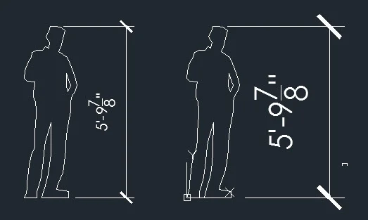
In the image below are two of the same scale figures drawn ini model space. On the left a dimension has been placed. The dimension has been set to a scale for printing at 1/4"=1'-0". At the right another dimension has been placed; the dimension has been set to a scale for printing at 1/8"=1'-0".
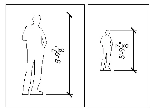
The same figures are shown in Layout view (paper space). The figures have been placed in two separate viewports. The left viewport has been scaled to 1/4"=1'-0". The right viewport has been scaled to 1/8"= 1'-0". Notice how figures are different sizes but the dimensions are the same. The is the result of AutoCAD's annotative features.
Text, graphic symbols and hatch can be setup to work similarly.
Objectives/Outcomes and Assessment Criteria
Students will acquire and demonstrate 1.) technical competency in working with annotations and annotative features, 2.) sense of craft through precision and care in the presentation of the work, 3.) design aptitude in the ability to solve an organization problem, 4.) judgment in the composition of objects to achieve clear graphic communication. 5.) consideration of limitations and constraints in the problem solving process.
Steps
ANNO.1. Open the Small House exercise that you completed previously. In this exercise you will be adding more content to that file.
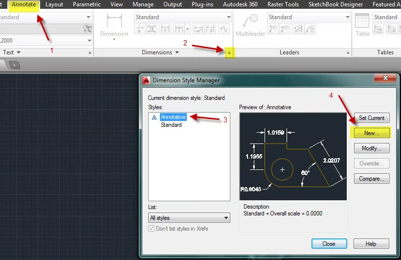
ANNO.2. Create a new Dimension style. You will fine the Dimension style window by 1.) going to the Annotate ribbon and 2.) selecting the small arrow on the Dimensions panel. To make a new dimension style click on the 3.) Annotative dimension style that is already in the file and 4.) click on New. You will be making a new style using the settings for the Annotative style.
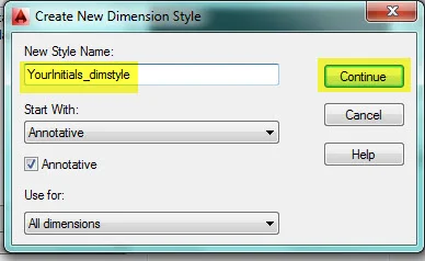
ANNO.3. Name the new style with your initials followed by dimstyle. Jake Taylor would name his dimension style JakeTaylor_dimstyle.
ANNO.4. You will be editing the settings so that the dimensions look like the one below. There are many settings and there are different styles used in various design disciplines. The dimension style below is typical for architectural drawings.
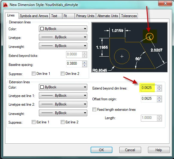
ANNO.5. Click on the Lines tab to change the value for the Extension beyond dim lines as shown below. Notice how the graphic in the preview window changes when you change the value.
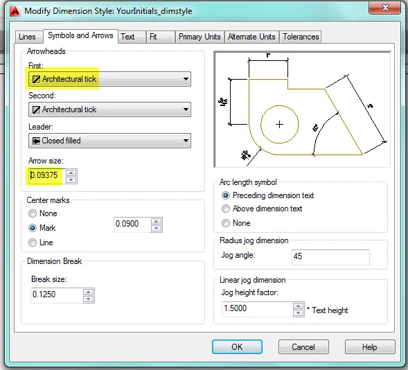
ANNO.6. Click on the Symbols and Arrows. Change the arrowhead type and the size of the arrowhead.
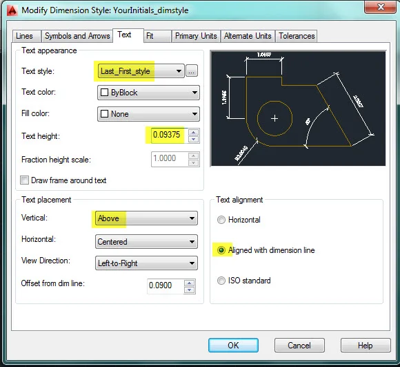
ANNO.7. Click on the Text tab, and change the style to the style you created for your titleblock. It should appear when you click on the arrow next to the style.
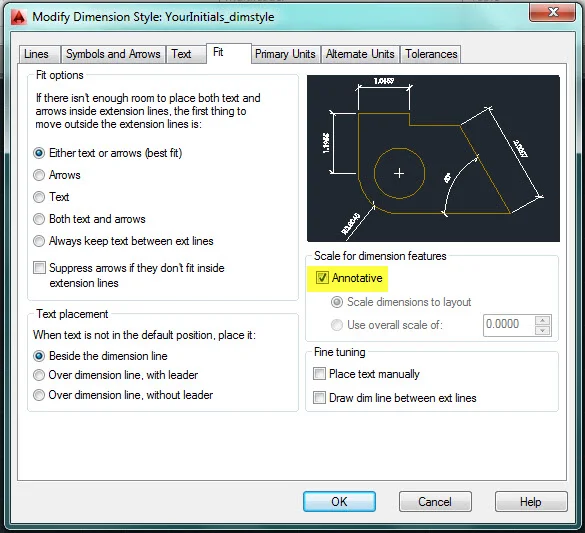
ANNO.8. Click on the Fit tab, and make sure that the Annotative box is checked. If you used the Annotative dimension style to create your style, it should already be checked.
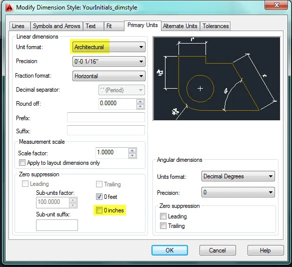
ANNO.9. Click on the Primary Units tab, and change the Unit format to Architectural and uncheck the 0 inches box under Zero suppression. By unchecking the box, a dimension will appear as 7'-0" instead of 7'. This makes it clearer the dimension is 7 feet instead of 7 inches.
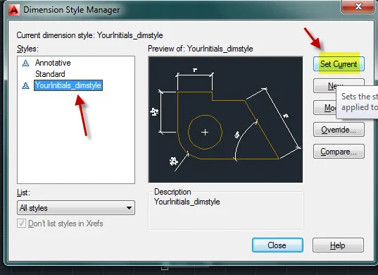
ANNO.10. The other settings can remain. Click on Ok. Set your new style to be the current style and close the window. Now any new dimension that you make will be your new style.
ANNO.11. Create the following layers: G-DIM, color 6. G-ANNO, 7.
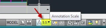
ANNO.12. The current annotative scale is probably 1:1. Set your annotative scale to 1/4"= 1'-0". This is the scale of your viewports in Layout view (paper space). If you don't change this setting, dimensions will be tiny.

ANNO.13. The make room for the dimensions, turn all layers on and move the section and elevation down about 20 feet.

ANNO.14. Offset your outer square 24” to the inside and 24” to the outside. These lines will be guidelines for drawing the dimensions.

ANNO.15. Turn off all layers except the grid, walls, doors, and window layers.
ANNO.16. Set your current layer to the Dimension layer. Create a new horizontal dimension string that measures the overall building width. Create a new vertical dimension string that measure the overall building depth.


ANNO.17. Keep in mind that a space is always left between the dimension line and the walls or objects that you are dimensioning.

ANNO.18. Use the second guideline square to show dimensions that show changes in the exterior wall shapes. The plan below has changes in the profiles of the exterior walls on all sides except the top.

ANNO.19. Use the third guideline to draw the dimensions to the centers of windows, doors and columns.

ANNO.20. Turn on all layers before drawing the remaining dimension strings. Dimension and locate interior walls, columns and door center lines with dimension strings running horizontally and vertically. The strings should run continuously across the plan. Shift dimension strings as necessary so they are not on top of one another.

H.Skalska
ANNO.22. Next you will be making graphic symbols. Do this work in layout view because they will be very small.
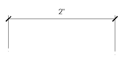
ANNO.23. The first will be a north arrow. Go to Google and search for images of north arrows. Look for a north arrow that you would like to draw. the choice is yours, but keep in mind that the north arrow needs to fit within a 1-inch square. Generally, north on a plan is upward. In your plan north will be in the upward direction.
ANNO.23. Your north arrow should be an inch wide. An example is shown below.

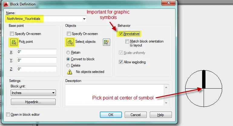
ANNO.24. Make a block of your north arrow. If you want to create a library of graphic symbols, you would use the WBLOCK command. This would send your block to its own file, but this block will remain in your file so you can use the BLOCK command. See image below for guidance. By checking the Annotative box you can insert the block in model space or paper space and it can be easily adjusted to the scale of your drawing.
ANNO.25. After you have made the block, all components will be grouped. If you click on the block, you will see that all parts are highlighted. A blue grip should appear at the center of the block.
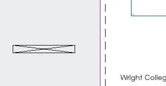
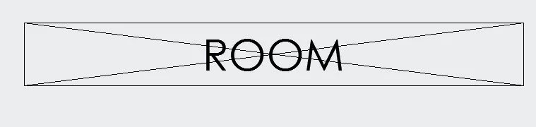
ANNO.26. The next block will be a room label. It will include a string of text that can be edited. A string of text that is embedded in a block but can be edited is called an Attribute. Off to the side of your titleblock construct a rectangle that is 1-1/2" wide by 3/16" high. Draw an X across the rectangle.
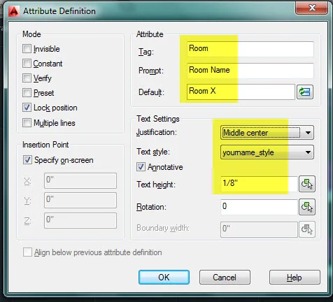
ANNO.24. You will be placing an attribute inside the box. An attribute is a piece of text that is embedded inside a block. The difference between a regular text string and an attribute is that the attributed can be edited after it has been formed into the block. Create an attribute by typing ATTDEF. This is short for attribute definition. See the image below for the atribute's settings.
ANNO.27. Click Ok and place the text at the intersection of the X. Once you click at the intersection, the text should move to center.
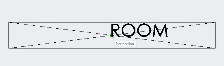
ANNO.28. Use the BLOCK command to create a block. See the image below for guidance.As noted below, select just the rectangle and the text. It is not necessary to select the X that crosses your rectangle. It was drawn to locate the center of the rectangle.

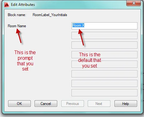
ANNO.29. When you click OK, the image below should appear. The window that you see is the result of placing an attribute in your block. This is where you can change the text. For now accept the default and cllick OK. If you double-click on the block, you should see the Edit Attributes window appear again.
ANNO.30. Erase the block and go to model space. Verify that your annotative scale is set to 1/4"=1'-0".
ANNO.31. Insert your room label into each of your rooms. The room names are your choice, but make sure that each room has a different name.
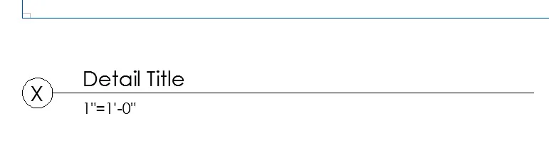
ANNO.36. Return to layout view. Construct another block with attributes as shown and described below. The circle has a diameter of 3/4". The line is 8 inches long. Use the ATTDEF command to define the attributes.
Attribute #1: Detail Title. The tag is Detail. The prompt is Detail Title. The default is Detail Title. The text is 1/4" high.The justification is Middle left.
Attribute #2: Scale. The tag is Scale. The prompt is Scale. The default is 1"=1'-0". The text is 3/16" high.The justification is Middle left.
Attribute #3: Detail Number. The tag is X. The prompt is Detail Number. The default is X. The text is 1/4" high.The justification is Middle Center.
Name the block DetailTitle followed by your initials. Place the pick point in a logical position.
ANNO.37. One of the first exercises was to construct a titleblock to use throughout the semester. The titleblock was planned for printing letter-sized sheets. Larger sheets are more typical. Common sizes are 11" x 17", 18" x 24", 24" x 36", 30" x 42" and 36" x 48". For the remainder of this exercise you will be setting up the drawing for printing 24"x36" sheets. The layout will be 36" wide and 24" high.
Return to the Titleblock page for a refresher. Follow the instructions for creating a page setup beginning at TB1.23. Most of the steps will be the same. Exceptions include the sheet size and the Drawing Orientation.
ANNO.38. On your new sheet create a string of text that is 1/2" high just as you had on your original titleblock. Center the title at the bottom of the sheet. Change the title for the sheet to Small House Project. Rename the layout tab to Plan Sect & Elev.
Delete the viewport that is there. Create two new viewports on the sheet. The size of the viewport can be adjusted to fit the content. In the left viewport show your plan. Verify that the viewport scale is 1/4"=1'-0". In the right view show the section and plan.
ANNO.39. Insert the detail title block below each of the three drawings. Change the detail title to describe the drawing. Number the drawings starting with 1 for the Plan, 2 for the section and 3 for the elevation. Change the scale to 1/4"=1'-0". You can edit the text by double-clicking on the block. Highlight an item in the list to change it. Also insert the North arrow with its center in alignment with the line of the detail title block.
ANNO.44. Print the layouts to pdf, save your drawing file, close your drawing file, and upload the pdf and the drawing file.


.
.
.