CCC Architecture
Programs in Architectural Studies at the City Colleges of Chicago
Exercise: Titleblock 1
Description:
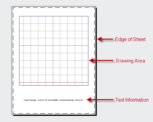
This exercise involves the creation of a sheet layout known as a titleblock. The titleblock establishes the layout of content on your sheet. It may include lines and text or may define what goes on different areas of your drawing. The titleblock you will be making for this exercises will be used for a number of future exercises. It is intended for letter-sized printing with a vertical orientation. There is 7" x 7" drawing area and a single text string that will include your name and information about the course and the exercise.
The titleblock may appear fairly simple, but there are many steps that are necessary to set up the drawing. These steps will save time later when you will be printing drawings.
The objectives of this exercise are to introduce the designer to:
1.) File types and file management, 2.) Drawing settings and sheet formatting, 3.) The paper space and model space work environments, 4.) Layers, 5.) Line precision and measurement, 6.) Text styles and multi-line text, 7.) Digital printing
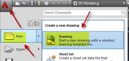
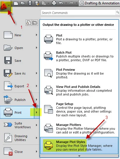
TB1.1. Create a new template file. 1.) In AutoCAD go the Application Menu icon, also known as the Menu Browser (big A in upper left corner). 2.) Click on New. 3.) Select the acad template. 4.) Select Open.
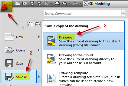
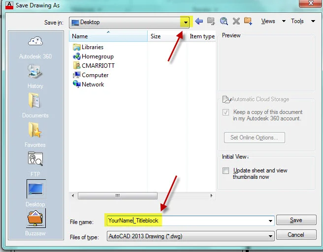
TB1.2. Save your file. 1.) Go to the Application Menu. 2.) Select SaveAs. 3.) Choose Drawing.
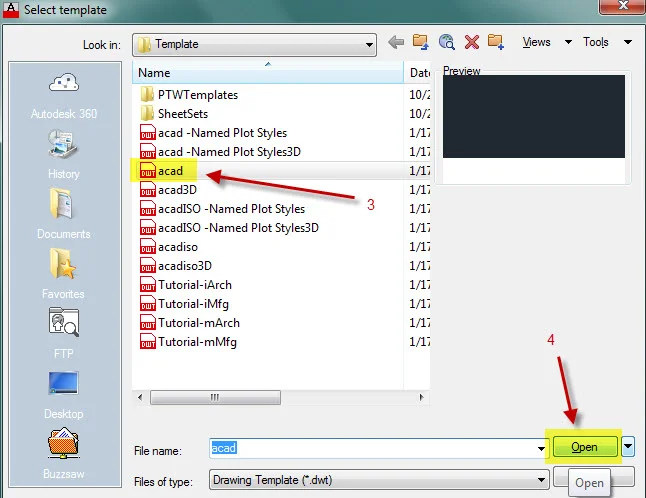
TB1.3. Name your file. 1.) Path to your external device or other storage location. Keep in mind that files stored on the computers in the ab will be deleted when you log-off. 2.) Name the file in the File name blank using your last name, first name + Titleblock. If Pat Smith was naming the file, the file would be named SmithPat_Titleblock.dwg. The .dwg is file extension for AutoCAD drawing files. If you look below your file name, you will see Files of type. The default (the setting that AutoCAD assumes unless you change it) will be a .dwg file.
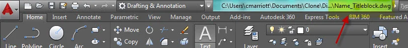
TB1.4. Check to see that the drawing is named as described above. You will see the file name at the top of the screen.
TB1.5. Experiment with some of the drawing tools. Make a composition of lines, rectangles, polygons, circles and ellipses. You will find icons for these objects on the Draw panel of the Home tab.

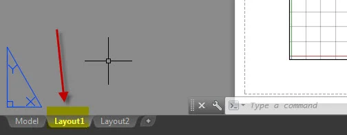
TB1.6. Most of the drawing done in AutoCAD is done in model space. The composition of shapes you have completed is in model space. With the default settings model space has a black background. When you are ready to print or set up a sheet for printing, this is done in paper space. To enter paper space left-click on the Layout1 tab at the bottom of the screen.
TB1.7. In paper space (or Layout view) you will see a mostly gray area with a white rectangle. The white rectangle is a letter-sized sheet with a landscape orientation. You are going to be create a letter-sized sheet with a portrait orientation. Before drawing anything you will need to set up a few things.
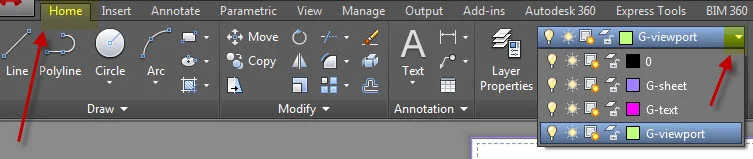
TB1.8. Begin with setting up some layers. In AutoCAD objects are drawn on different layers. Layers allow you to have control of the characteristics of objects in your drawings. You may, for example, want to turn of certain types of objects. You may want some objects to appear one way when printed and other objects to appear another way. Layers enabled you to have control in this way. To make layers open the Layer Manager which can be opened by clicking on the Layer Properties icon which can be found on the Home ribbon. You can also type LA at the command line.
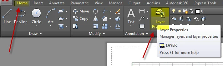
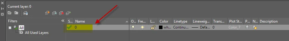
The Layer Manager will open. There will be one layer already in your file. It is layer 0.
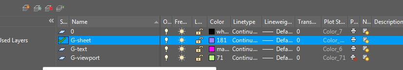
TB1.9. You will need to create some new layers. To create a new layer 1.) click on the New Layer icon. 2.) Rename the layer. Click on the new layer until it turns blue. 3.) Type in the new layer name. Name the first layer G-sheet. The edges of the sheet of paper will be drawn on this layer.
TB1.10. Create two more new layers named G-text and G-viewport. The "G" indicates that it is a graphic layer. The text will be drawn on the G-text layer. The 7"x7" box will be drawn on the G-viewport layer.
TB1.11. Change the color of layer G-text to magenta 1.) by clicking on the black box under the Color column to the right of the G-text layer, selecting the magenta color, and 3.) clicking on OK. Anything drawn on layer G-text will be magenta on the screen.
Change the color of the G-sheet and G-viewport layers as well. The colors are your choice.

TB1.12. Change the setting of the G-viewport layer so it does not print. Click on the Printer icon to change its setting. Objects drawn on the G-viewport layer may be visible on the screen but will not print.

TB1.13. Notice that the layer 0 has a green check mark next to it. The green check mark indicates which layer is the current layer. Anything new that is drawn will be on the layer with the checkmark. 1.) Make the G-sheet layer the current layer by double-clicking on the blue layer icon on the left side of the layer name. You should notice that a checkmark appears. 2.) Close the Layer Manger by clicking on the X.
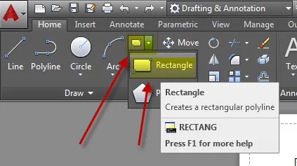
TB1.14. Now we are ready to begin drawing the sheet. The default orientation is landscape. Yours will be portrait. Start by drawing a rectangle that represents the perimeter of the sheet.
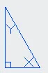
TB1.15. AutoCAD operates on a coordinate system. By default an X-axis runs horizontally, and a Y-axis runs vertically. The origin point is 0 on the X-axis and 0 on the Y-axis. You might notice an icon like the one below indicating the relationship of the two axes.
TB1.16. You will be prompted to select an initial point for your rectangle. It is possible to simply click on a point on the screen, but it would be better to specify a coordinate point. Input a zero, then a comma, then another 0. The lower left corner of your rectangle will be at coordinate point 0,0.
For the second point input 8.5, then a comma, and 11. This will set the upper right corner at coordinate point 8.5,11. This makes the rectangle represent a letter sized sheet of paper which is 8.5" wide by 11" high.
TB1.17. So that you can see the entire rectangle, type Z for zoom and select the Extents option.

Your new rectangle will be visible on the screen. That rectangle represents your sheet of paper.
TB1.18. Erase the existing viewport which shows the content in model space. 1.) Click on the viewport, and 2.) select the Erase icon which you can find on the Home ribbon. You will be generating a new viewport layer.
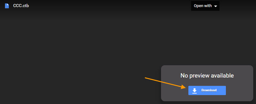
TB.19. In preparation for printing you will need to download a file that controls the lineweights in our printed sheets and place it in a folder where AutoCAD looks for these types of files. One has been created for you at the following link: CCC.ctb. Once you have gone to the link click on the Download button.
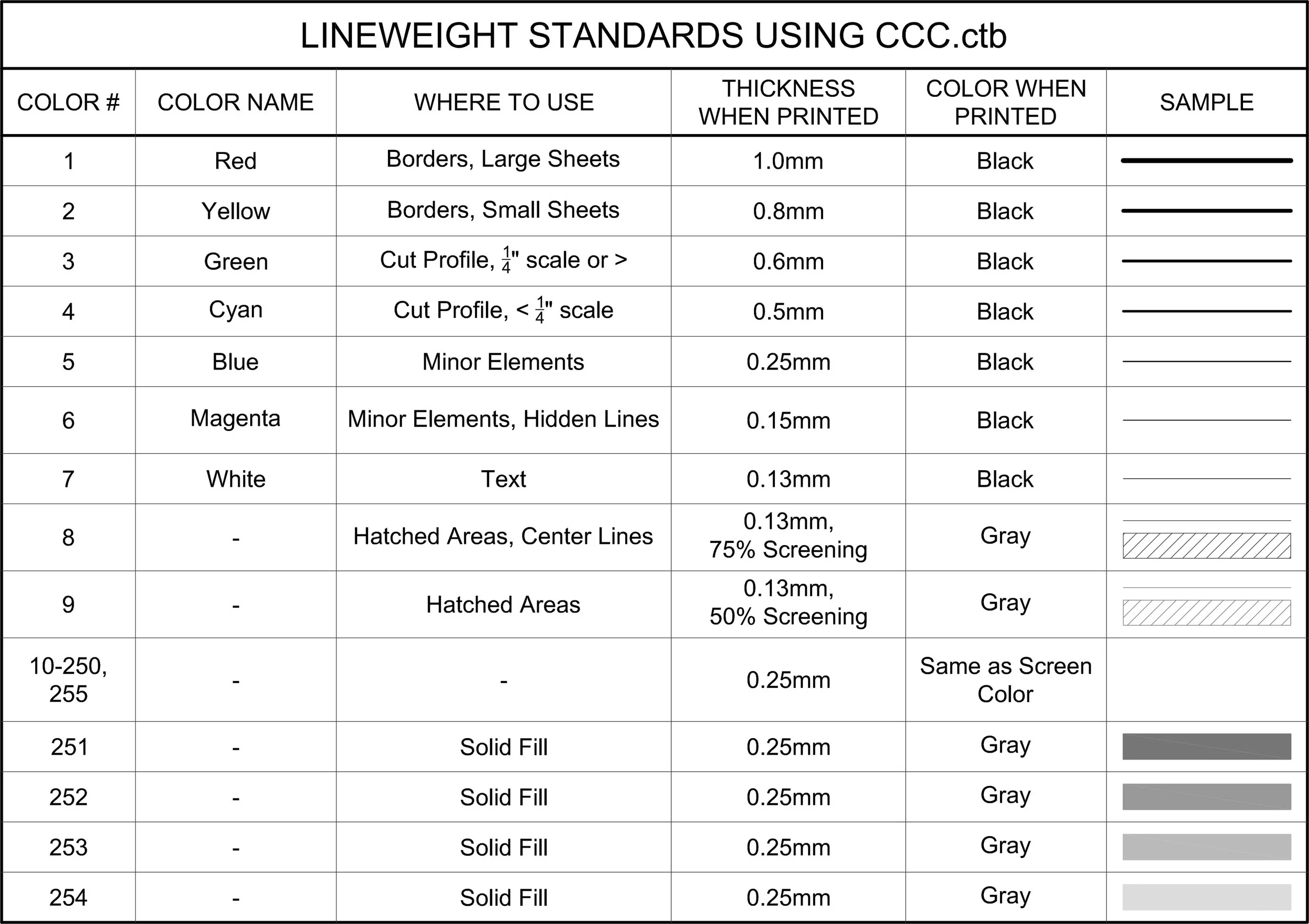
The table below illustrates how the setting affect the colors.
TB1.20. The downloaded file called CCC.ctb now needs to move to the proper folder so AutoCAD can find it. Look for the file in the download folder on your computer. When you find the file, click on it and then right-click. Select Copy.
TB1.21. Find the manage plot style folder as shown below. Once you are in the folder, right-click and select Paste. You should see the file in the list. Close the window by clicking on the X in the upper right.
Note: if you are working in a computer lab, you may need to complete this step every time you log-on. It may save you time to put a copy of CCC.ctb on your external drive.
TB1.22. Now you are ready to set up the file for printing. In your Layout view zoom out by typing Z and choosing the Extents option so you see the entire rectangle with the portrait orientation. Open the Page Setup dialog box.

TB1.23. Create a new layout by 1.) selecting New and 2.) giving a name to your layout. Name the setup with you last name and first name followed by Layout.

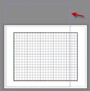
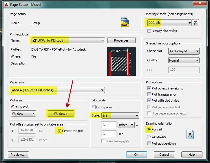
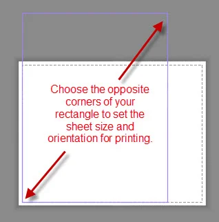
TB1.24. When you click OK, you will be taken to the window below where you can edit the settings of the page setup. Make the setting changes shown below. If you don’t see DWG To PDF.pc3, you can choose another pdf maker. Also, note that when you change the Plot Area from Layout to Window, you will see the Window button appear (as shown with the red arrow in the image below). When you click on that icon you will be taken to your layout. In your layout click on the lower left and upper right corners of your portrait oriented rectangle.
TB1.25. When finished, click OK. Then set the new page setup to current by clicking on Set Current. Click OK when finished. You should see that the white area is now aligned with your rectangle. Now the page is ready for printing, but there are a few more steps needed before we do.

TB1.26. The drawing area in our layout view will be a 7"x7" square. The square will be centered left to right and 1.5" from the top of the page. Before drawing the square, change your current layer to G-viewport.
TB1.27. Next we'll be inputting objects precisely using the coordinate system.
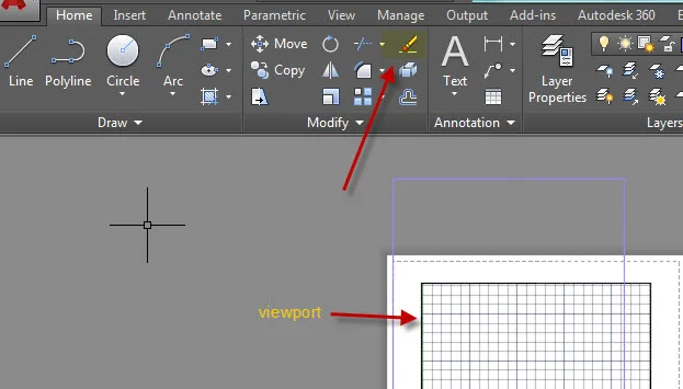
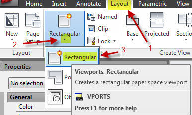
Now you are ready to create a viewport. A viewport is like a portal into model space where most of the drawing occurs. The drawing area is inside the viewport. To make a viewport go to the Layout ribbon and select a rectangular viewport.
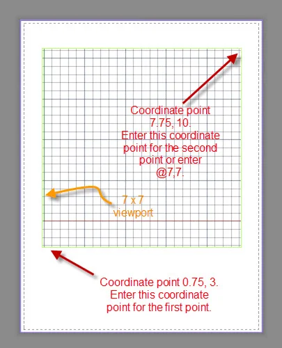
TB1.28. You will be asked for two corners of your layout rectangle. The lower left corner of our rectangle will be at coordinate point .75, 3 [.75 comma 3]. To select the upper right corner for the viewport you need to input the @ symbol first. This will establish a position relative to the point at .75, 3. Input @7,7 [@ symbol + 7 comma 7] for the other corner. Anything that you have drawn in model space will appear in the viewport.
Note: there is an inconsistency in the input of the second point for a rectangular viewport when compared to the input of a rectangle. For the viewport you need to enter an @ symbol first to find a point relative to the first. For a rectangle you don't.
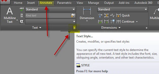
TB1.29. The last step before printing is adding the text string below the viewport. First, make a new text style. Open the Text Style dialog box as shown below or type ST at the command line.
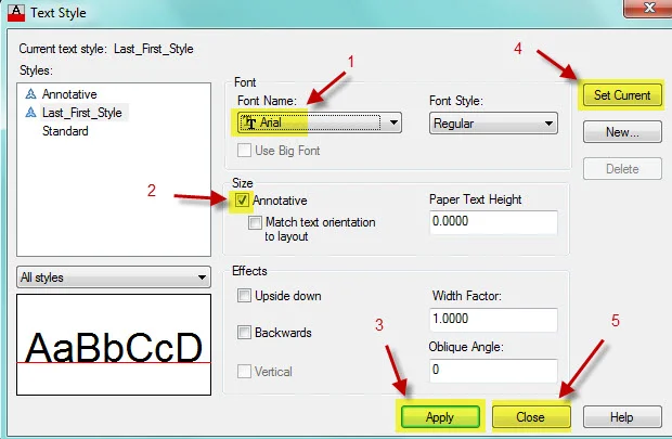
TB1.30. Create a New text style and name the style with your name and Style.

TB1.31. Edit the settings for your text style. Choose any font except Arial. It is recommended that you choose a font that is fairly easy to read.
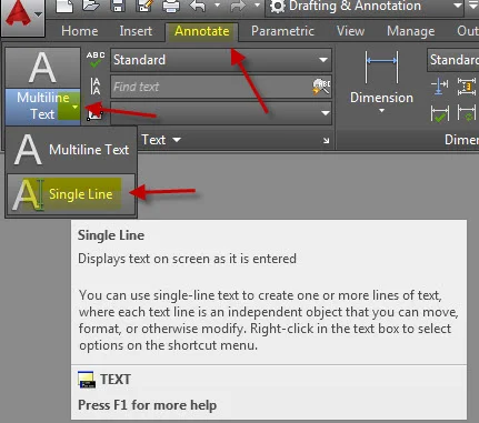
TB1.32. Now you are ready to add the text line. Set your current layer to G-text. Choose the Single Line text icon that can be found on the Annotate ribbon.
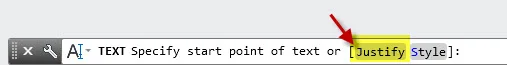
TB1.33. You will be prompted for a point. Instead of inputting the point select the Justify option.
TB1.34. Then select MC for Middle Center. This will allow you to precisely center the text.

TB1.35. The text will be centered left to right and it will be 1.5" above the bottom of the sheet. Input 4.25,1.5 [4.25 comma 1.5] to place the text. When prompted for the height of the text, input 0.125. Press enter. Accept the 0 value for rotation by selecting Enter. Next you will be asked to input the text. Begin by typing Harold Washington College. Then click outside of your text. You might notice that the text is now much smaller on the screen. To add more text double-click on it. Add the course name Architc 170 or Cad Tec 170 as well as the semester, the exercise name which is Titleblock Exercise, and your name. Separate each component with a symbol like an asterisk, bar, hyphen, etc.
Harold Washington College | Architc 170 | Spring 2000 | Titleblock Exercise | Pat Smith
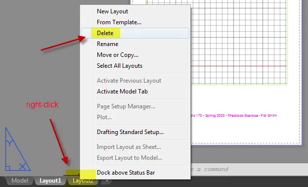
TB1.36. Right click on the Layout 2 tab and delete it. You will be using the layout that you created in the Layout1 tab.
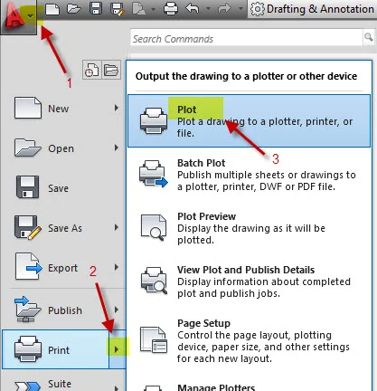
TB1.37. The sheet is now ready to print. To initiate the plotting go to the Plot window as shown below or type PLOT at the command line.
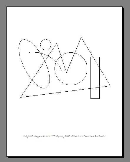
TB1.38. The Plot window looks very similar to the Page Setup window. All of the settings that you made during the Page Setup steps should be visible in the window because you set your new setup to be current. Click on Preview at the bottom of the screen. Your preview should look something like the image below. Notice how the viewport square does not print. This is because we set the viewport layer to not print. Also, notice that the text appears in as black text; this is because CCC.ctb was used to make the print. The color assigned to the text was magenta which prints black.
TB1.39. Close the preview by pressing Enter or clicking on the X at the top of the Preview window.
TB1.40. Click on OK. You will be making a digital print in the form of a pdf file. The pdf is the digital version of the paper print. You will be asked to locate the file and give it a name. Locate the file by Browsing to the desktop or external device. Name the file with the same name as your drawing file.

TB1.41. Save your AutoCAD file. Close the file. Always close the file before you submit it.
TB1.42. You will be submitting all of your work for this class to a Google Drive folder. Visit the Portfolio page and complete the Section under the blue bar titled "Setting up an Archive Using the Google Drive". If you are unable to complete this during class today, make sure that you save the files to an external devise or that you email them to yourself so you don't need to redo the work.
TB1.43. Upload BOTH the drawing file and pdf to your Google Drive folder.
Note: it is highly recommended that you redo the entire exercise on your own.