CCC Architecture
Programs in Architectural Studies at the City Colleges of Chicago
Units & Aggregations
This is a multi-week project where you will be designing a mid-size residential structure. The book titled Conditional Design: An Introduction to Elemental Architecture will be a referenced for this work. For this project it will be important that you have frequent discussions and receive feedback upon the completion of each part.
Part 1 - Connection Elements
The first part of this series involves the modeling of stairs. Refer to page 13 of the Conditional Design book. There you will see three stair conditions: a straight run, an L-shaped stair and a U-shaped stair. You are asked to draw one of each.
UA.1.1. Create a new Rhino file using the Large Objects - Feet template. Name the file with your name followed by Connection Elements. Joe Smith would name his file JoeSmith_ConnectionElements.
UA.1.2. Turn on the Grid Snap setting and Ortho.
UA.1.3. Terms:
- Risers: the vertical surface of a step
- Treads: the horizontal surface of a step
- Rise: the full height of all risers
- Run: the full length of all treads
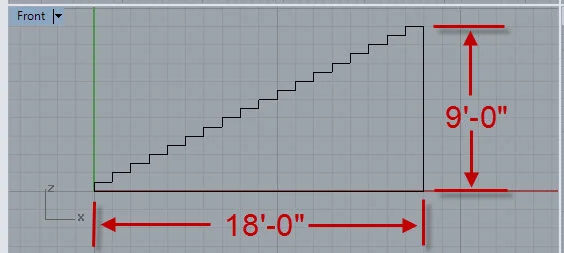
In the front view construct the profile of the stair using the Polyline command/tool. The measurement of risers and treads varies, but to keep things simple for your project, yours will be 6" and 12". The rise will be 9 feet and the run will be 18'-0". If you make them as lines instead of polylines, you can use the JOIN command to turn them into a closed curve. The shape needs to be a closed polyline so that it can be extruded.

UA.1.4. Extrude the curve and cap the extruded polysurface to produce a closed polysurface. The extrusion distance should be 3'-0", the minimum width of a residential stair.
UA.1.5. In the same file repeat these steps for an L-shaped stair and a U-shaped stair. Use the same riser, tread and rise dimensions. You might want to sketch out the stair before drawing it in Rhino.
UA.1.6. Upload your file to the Google Drive.
Part 2 - Creating Units
In the Operatives Design exercises you manipulated forms. Now you are asked to take those form-making principles and focus on making units of space. One of the three units will become a two-story residential apartment that you develop further.
UA.2.1. Create a new Rhino file using the Large Objects - Feet template. Name the file with your name followed by Units. Jan Smith would name her file JanSmith_Units.
UA.2.2. In the same file create three units. Each unit must:
- Combine at least 2 base volumes using operatives from the Operative Design book.
- Be hollowed with walls and floors that are 1 foot thick. The SHELL command is one way to hollow out a volume.
- Have openings. Pages 64-83 of the Conditional Design book may give you some ideas about placing openings. Openings can be made while you are using the SHELL command or later by subtracting (Boolean Difference) shapes from the enclosing planes of your volumes.
- Must integrate the stair connectors from Part 1. Each stair should be used once. The stair element dimensions were intended to work with a 9'-0" floor to floor rise. In the image below two 10'-0" high volumes have been overlapped by 1 foot. Notice how the floor on one volume aligns with the roof of another in the image below. To bring a stair from one file to another use the Copy (Ctrl + C) and Paste (Ctrl * V).
IMPORTANT: You are required to have 3 units. Each unit will be made of 2 spatial volumes and one stair. One unit will have 2 volumes and the straight run stair. One unit will have 2 volumes and the L-shaped stair. One unit will have the U-shaped stair. All three units will be in the same Rhino file.
Pages 20-39 in the Conditional Design book illustrate how you might approach this problem. You are asked to invent your own connection solutions.

The image below shows a possible configuration of a unit. In order to make this unit an enclosed set of spaces, more walls and definition of rooms will be required, but for the moment you can leave your units open and undefined as shown below. What is important at this point is that your connector elements (stairs) are connecting the floors of your volumes as shown above.

UA.2.3. Use the Group command to join the elements of each unit into one object. Note: you can ungroup a group by typing Ungroup at the command line. This keeps things together, but allows you to edit the individual parts more easily than the Boolean Union command.
UA.2.4. Upload your file to the Google Drive.
Part 3 - Unit Aggregations
One of the three units from Part 2 will be chosen to advance to this part. Wait for some feedback on choosing before proceeding with this part.
UA.3.1. Make a copy of your Context Model file and name the new file with your name followed by Aggregation Study. Jack Jones would name his file JackJones_AggregationStudy.
UA.3.2. Create a new layer called Property Lines. Make the new layer the current layer by double-clicking on it. A green checkmark will appear.
UA.3.3. Choose a place to site your project in one of the two middle blocks. It is recommended that you choose a site on the north side of a street. This will allow you to have a southern exposure which will give more opportunity to work with sunlight. Your site will be 100'-0" x 100'-0". At least one edge must be along a street. Clear or move existing buildings to make room for your site. In the image below a 100' x 100' square has been drawn on one of the middle blocks. The box is on the north side of a street.

UA.3.4. Draw lines indicating the boundaries of your site.
UA.3.5. Create another layer called Aggregation 1. Assign a the White Matte material to the layer and choose a color for your layer. Make the new layer the current layer. Copy and paste one of the units from Part 2 into your file.
UA.3.6. Change the layer of the unit by clicking on it, and changing its Layer in the Properties window. Put the spatial unit on the Aggregate 1 layer.
UA.3.7. Refer to pages 112-131 in the Conditional Design book. You do not need to use the specific operatives shown on those pages. Arrange at least 8 units in an aggregation that follows a pattern. They can be side by side or stacked, rotated, mirrored. All units must have access to the street. You can create a walkway or courtyard within your site. If it helps, turn off the layers you aren't using. Your aggregation can not be higher than 30'-0". The image below shows one arrangement of the units.

UA.3.8. Note: all work for Part 3 should be done in the same Aggregate file. Use your layers to control visibility. Create another layer called Aggregation 2 and assign the White Matter material with a color of your choice. Make a copy of one of the units that you used in Aggregation 1. Change the layer of the new copy to Aggregation 2. Turn off the Aggregation 1 layer.

UA.3.9. Make another arrangement of your unit. Again, use 8 of the units to form your aggregation.
UA.3.10. Repeat the steps above for a third aggregation.

SU.3.11. Upload the aggregation file to your Google Drive folder.
Part 4 - Enclosure
In this part you will be selecting an arrangement from Part 3. It is recommended that you get some feedback before proceeding.
UA.4.1. Make a copy of your aggregation file. Name the new file with your name followed by Enclosure. Choose one of the three schemes from Part 3 to develop further. Turn off or erase the two arrangements that you won't be using.
UA.4.2. You need to be able to isolate the unit that makes up your aggregation so that you can work on it. Make a copy of one unit. Place the copy on the side of the context model. Now that the placement of the units is set, you can continue to define the enclosures for each unit. If all units will have the same enclosure, then you can edit one unit and copy the edited unit throughout. Get some feedback concerning your ideas for enclosure before completing this section. In this part you will need to:
- Add horizontal and vertical planes to serve as enclosing elements.
- Add openings
- Add glass to your openings. Show the glass as 1" thick volumes. Center the 1" panels in the wall. Create a layer for your glass and assign the glass material to it. You will find this under the Transparency menu in the Materials. Change the value of Transparency to 80% so that you see a tint where the glass is.
The image below shows the addition of walls and openings.

UA.4.3. Group all of the parts of your unit.
UA.4.4. Move the unit over to the aggregation within the context model. Replace all of the units with your new one.
UA.4.5. Save your file. Upload the file to your Google Drive folder.
.
.
.