CCC Architecture
Programs in Architectural Studies at the City Colleges of Chicago
Rendering
For this exercise you will be creating rendered views of your context model. This rendering work should be done after you have completed your Enclosure work.
PART 1 - Top Views
[In the previous exercises you were asked to assign new materials to your building. For this set of exercises it is important that the context color is different from your building. When you render your project, you want to be able to differentiate it from the context.]
R.1.0. Create a copy of your project file and name it with your name followed by TopViews.
R.1.1. The first views will be a set of top view. Go to the Top view. Type in Zoom at the command line, and choose the Extents option.
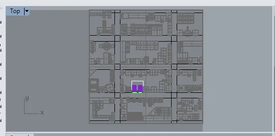
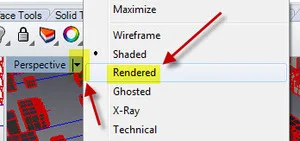
R.1.2. Change the Visual Style to Rendered to see your materials. You are welcome to make changes to your materials.
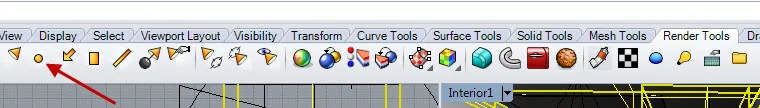
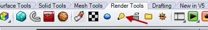
R.1.3. Next you will be rendering the Top view. Click in the Top viewport to make sure it is the current viewport. Select the Render tool which you will find by clicking the Render Tools tab.

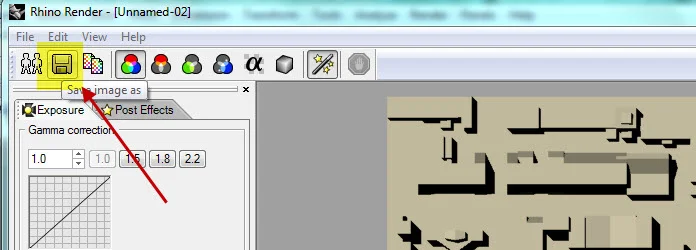
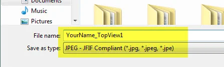
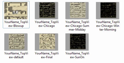
R.1.4. Shadows should appear in your image. Save the image. Name your file with Your Name followed by TopView-default. The file type for this image and all other images should be a jpg.
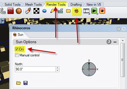
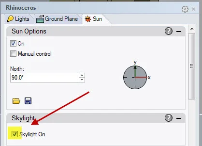
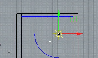
R.1.5. Next you will be making adjustments to the position of the sun to control the depth and direction of the shadows. Turn on the sun as shown below.
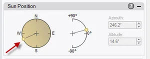
R.1.6. In the Sun Position panel you can see the position of North. By default North is up when looking at your model from the top. The red arrow below shows the location of the sun.
R.1.7. Render the view again. Save the file with Your Name and TopView-SunOn.
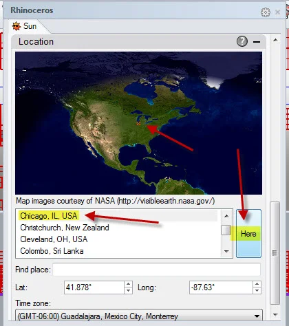
R.1.8. You can control the direction of the sun by changing Location. In the Sun properties window scroll down to the Location panel. Change the location to Chicago by selecting it from the list. Click on Here to reset the time for that location.
R.1.9. Render the view and name it with Your Name followed by TopView-Chicago.
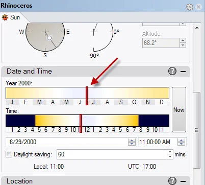
R.1.10. You can also control the direction of the sun by changing the Date and Time. In the Sun properties window go to the Date and Time panel. Change the month to a summer month. Drag the bar so that the sun is set to June/July. Change the time so it is close to noon.
R.1.11. Render the view and save it as YourName_TopView-Chicago-Summer-Midday.
R.1.12. Adjust the month to a winter month in the morning. Render the view. If it is completely dark, adjust the time. Save it as YourName_TopView-Chicago-Winter-Morning.
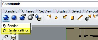
R.1.13. Next we'll be making some changes to the rendering settings. Put your cursor over the render button and right-click.
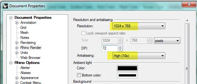
R.1.14.Make the changes shown below. Anti-aliasing smooths out curves. Adjusting the resolution will also improve the quality of the image.
R.1.15. Go to the Sun Properties window and check the box next to Skylight. This setting will add general illumination to the image.
R.1.16. Create an additional image with date, time and location settings that you feel are best by adjusting the time, date and location as necessary. Render the image. Save the file as YourName_TopView_Final. This rendering will take a little longer.
R.1.17. Zoom closer to your building on the site and create an additional rendering using the same settings. The edges of your context model should not be visible. Save the file as YourName_TopView_Blowup
R.1.18. Your should have 7 saved images from the Top View.
R.1.19. Upload the 7 images and the Rhino file to your Google Drive folder.
Part 2 - Aerials and Street Views
R.2.0. Create a copy of the file from part 1 and name it with your name followed by Aerials&Streetviews.
R.2.1. In the Perspective view compose an aerial view of your context model. The project you have developed should appear in your view. The edges of the ground should not appear, just the building and the surrounding buildings. Zoom in as necessary.

R.2.2. Change the Visual Style to Rendered to see your materials.
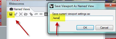
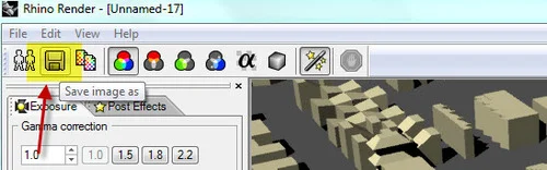
R.2.3. Save the view as shown below.
R.2.4. Save the view and name it Aerial. Keep in mind that you can return to any views that you have saved.
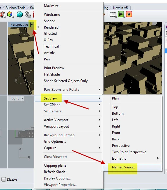
R.2.5. You can return to any views that you have saved by clicking on the thumbnail image. Another way to get to the Named View window is to type NamedView at the command line. All rendered views in the remainder of these assignments must be from named views. This is different from naming an image file after you have rendered it.
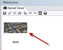
R.2.6. Next you will be rendering the Aerial view. Click in the Perspective viewport to make sure it is the current viewport. Open the NamedView window and double-click on the thumbnail image. This will reset the view in case you changed it.
R.2.7. Render the image at a low setting. The resolution Could be set to 640x480. Anti-aliasing should be set to Normal.
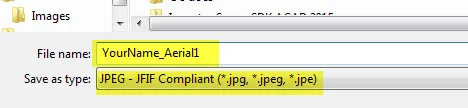
R.2.8. Save the rendered view. Name the view with Your Name followed by Aerial 1. Choose the jpg format.
R.2.9. Render two more views from the same position. Each rendering should integrate different settings for the date and time. As a result the shadows should appear different. Name the views with Your Name + Aerial2 and Aerial3.
R.2.10. Choose one of the renderings to run at a higher quality. Change the rendering settings to a higher level. The Skylight should be turned on, anti-aliasing should be set to High, and the Resolution should be set to 1024 x 768. Re-render the view at name the view with Your Name + Aerial-Final.
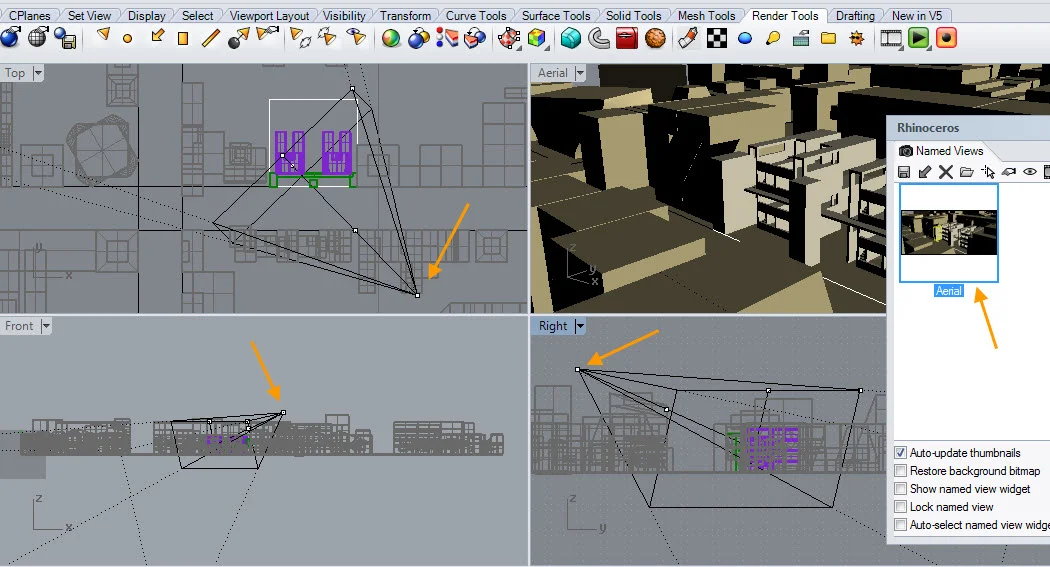
R.2.11. In the preceding steps you composed your view in the Perspective viewport and you saved the view as a named view. When you saved the view, Rhino saved the view as a camera with a camera position and a target. Reset the view to the named view. and press the F6 key which you will find along the top of your keyboard. The camera will appear in each viewport. An orange arrow points to the camera position in the Top, Front and Right views.
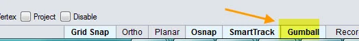
R.2.12. To reposition the camera you can use the Gumball. Check to see that the Gumball is on.
R.2.13. Then click on a camera control point. Move the camera by dragging the arrows of the gumball.

R.2.14. The changes should be visible in the Perspective view. If you have made changes that you would like to save, you can either save and over-write the existing view or make a new one. You do not need to make changes to your Aerial view at this time, but keep these steps in mind if you want to make adjustments to future camera views. Pressing F6 again hides the camera view. Reminder: if you change the camera position and you would like to save the changes, you need to create a new named view or overwrite an existing one.
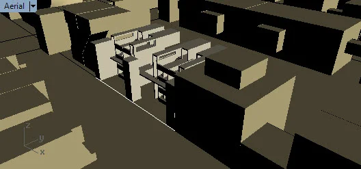
R.2.15. For the next two images you will be creating views at street level looking up at your building. You know how to compose a view, name the view and adjust the camera view using the Gumball. There is another way to locate a view. This method places a camera in the view. First, go to your Perspective view. Position your view so you are above a street looking down at your building as shown in the image below.
R.2.16. Click on the Properties window. Make sure that nothing is selected in your model. Next click on the Place button below Camera and next to Location. Then click on a point on the street.
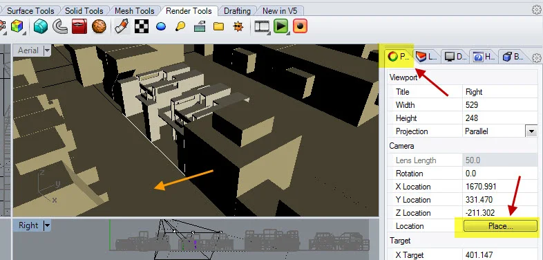
R.2.17. The Perspective view should automatically go to that position.

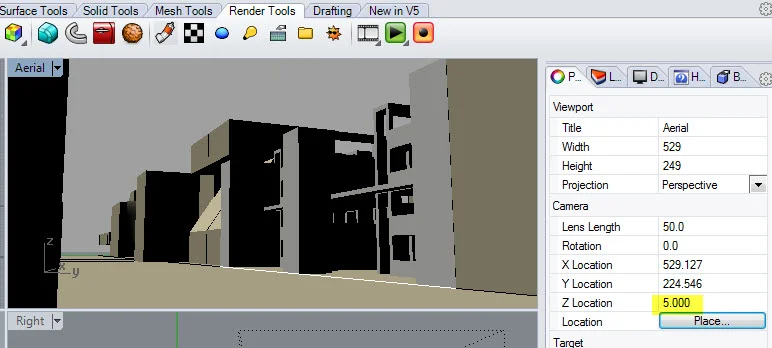
R.2.18. Holding town the Ctrl + Alt key while dragging the right-mouse button will allow you to change the target. Changing the Z Location to 5 feet will approximate the view seen by a person standing on the ground. Holding the Ctrl key and right-mouse button will allow you do zoom in and out. Your image should include the adjacent buildings.
R.2.19. When you are pleased with the view, save it as a named view. Name the view Streetview A.
R.2.20. Render the street view three times. Each rendering should have different shadow angles and should be run a the lower settings. Name the rendered images with your name followed by StreetviewA-1, StreetviewA-2 and StreetviewA-3. Run one of the renderings at a higher level and name the view with Your Name + StreetviewA-Final.
R.2.21. Create a second street view from a different position on the street. Name the view StreetviewB. Render the street view three times at a low settings with different shadow angles. Name the rendered images with your name followed by StreetviewB-1, StreetviewB-2 and StreetviewB-3. Run one of the renderings at a higher level and name the view with Your Name + StreetviewB-Final.
R.2.22. Upload your images and Rhino file to your Google Drive folder. For Part 2 there should be 12 images (4 aerial views and 8 street views) and 1 Rhino file.
Part 3 - Exterior Views
In this part you will be creating more renderings, but closer and within the exterior spaces of your building.
R.3.0. Create a copy of the Rhino file from the previous part and rename it with your name followed by ExteriorViews.
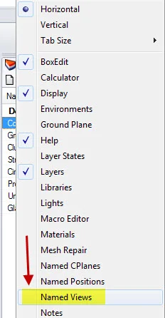
R.3.1. You may find it useful to add the Named View panel to your workspace. On the right side of your screen, select the Options button.
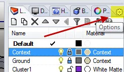
R.3.2. Place a check next to the Named Views panel.
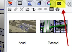
R.3.3. A camera icon will appear as a tab. Click on the icon to open the Named View Panel. The saved named views will appear as thumbnails.
R.3.4. For this part you will be creating exterior renderings of your building. The goal will be to generate compositionally dynamic views activated through light and shadow. Take care to compose your views.
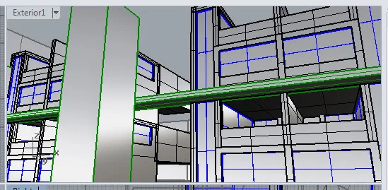
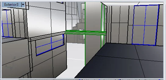
R.3.5. Using the methods described in parts 1 & 2 create a new named view of your building’s exterior. The view should be 5 feet above ground level, relatively close to the building, and with a target that looks up toward the top of your building. Name the view with your name followed by ExteriorA.
R.3.6. Render your ExteriorA view with 3 different shadow conditions using low rendering settings. Name the rendered images with your name followed by ExteriorA-1, ExteriorA-2 and ExteriorA-3. Choose one to render at a higher quality (resolution-1024x768; antialiasing-high). Name the rendered image with your name followed by ExteriorA-Final.
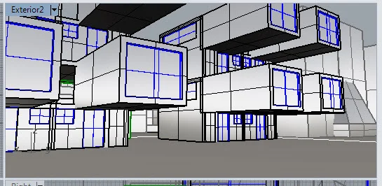
R.3.7. Create a named view that is on your building’s site, 5 feet above ground level, but still outside the building. Name the view with your name followed by ExteriorB.
R.3.8. Render your ExteriorB view with 3 different shadow conditions using low rendering settings. Name the rendered images with your name followed by ExteriorB-1, ExteriorB-2 and ExteriorB-3. Choose one to render at a higher quality. Name the rendered image with your name followed by ExteriorB-Final.
R.3.9. Create a named view that is on your building’s site, at a higher level terrace or exterior walkway The image should capture elements of your building and the context. Name the view with your name followed by ExteriorC.
R.3.10. Render your ExteriorC view with 3 different shadow conditions using low rendering settings. Name the rendered images with your name followed by ExteriorC-1, ExteriorC-2 and ExteriorC-3. Choose one to render at a higher quality. Name the rendered image with your name followed by ExteriorC-Final.
R.3.11. Upload your images and Rhino file to your Google Drive folder. For this part there should be 12 images and 1 Rhino file.
Part 4 - Interior Views
In this part you will be exploring interior views and artificial lighting.
R.4.0. Make a copy of your Rhino file from the previous part and rename your file with your name followed by InteriorView.
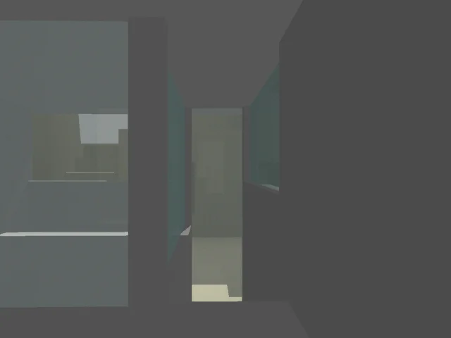
R.4.1. Create a named view from the interior of your building. It is challenging to place the camera within an interior. You will need to use the techniques described in the previous parts for this. That includes placing the camera through the Properties window, using the Gumball and using the Ctrl, Shift and Alt keys to make adjustments. A good image includes layered spaces. For example, you may be positioned in one room, but you see another room beyond, and perhaps an exterior space beyond that one. Avoid views looking only one room (not very interesting). Save the named view as InteriorA.
R.4.2. Render one image with sun light on. You can run the rendering at a low setting. Name your rendered view with your name followed by InteriorA. If you are not entirely pleased with the rendering, don’t worry yet. You will be working on this.
R.4.3. Create two more named views from interior positions. Save the named views as InteriorB and InteriorC. Render each view with natural light. Name the rendered views with your name followed by InteriorB and InteriorC.
R.4.4. Choose one of the interior views to develop further. Choose one that is well composed and has a layering of spaces.
R.4.5. Next you will be adding lights. One type of light is a point light. It emits light from a single point in all directions. You will find the lights on the Render tab.
R.4.6. Place the light by clicking in one of the viewports that is in one of the spaces that shows up in your chosen view. You may find that placing the light in the Top view is best. You will see a symbol representing the point light. The light can be moved by clicking on it and using the Gumball.
R.4.7. After you place the light, you can adjust its height using the Gumball. Just select on the light, and in the Front or Right view, click on the arrow of the Gumball. Drag the light or input a value for the distance to move the light.
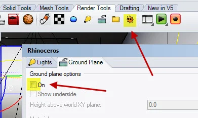
R.4.8. Turn off the sun. Uncheck the box to turn off the sun. This will allow you to concentrate on the artificial light.
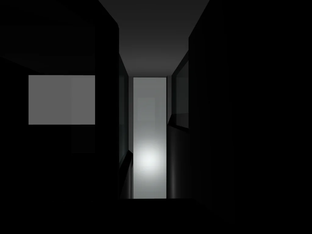
R.4.9. Render the view. Low rendering settings can be used. Name the rendering with your name followed by Interior(A B or C)-1_pointlight.

R.4.10. For the next few images you will be adding lights and making changes to the lights in your model. One problem with the light in the image above is that it is too bright. To resolve this problem the intensity can be adjusted. You can click on the light and in the Properties window adjust the intensity.
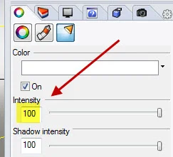
R.4.11. The intensity was set to 25 in the image below. Render your image with the intensity adjusted. Name the rendering with your name followed by Interior(A B or C)-2_IntensityAdjusted.
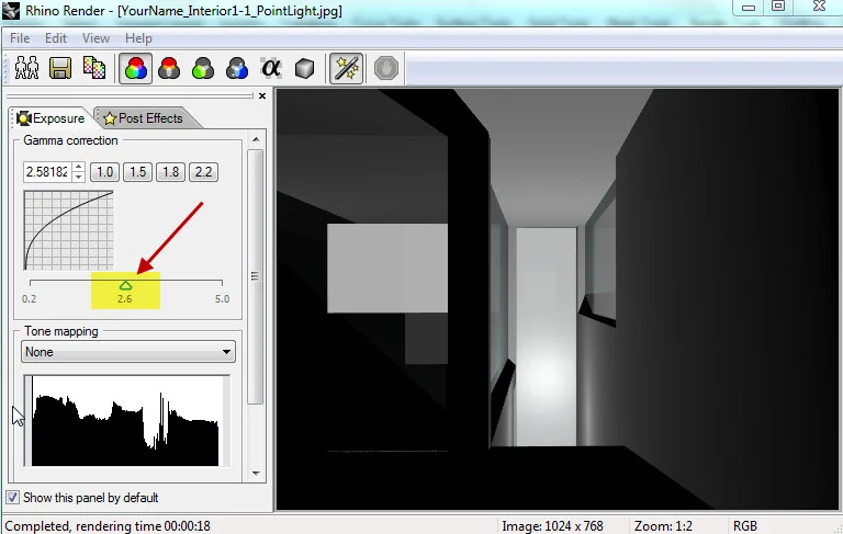
R.4.12. Make adjustments to the Gamma values. This setting can be useful if your image appears dark. Re-save the rendered image with the gamma adjusted. Name your file with your name followed by Interior(A B or C)-3_GammaAdjusted.
R.4.13. To see a list of all of the lights that are currently in your model, click on the light bulb.
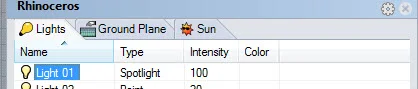
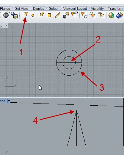
R.4.14. There are other types of lights. One is a spotlight which emits a cone shaped light area from a point. It has a position and a target similar to a camera. It can be difficult to place and direct a spotlight. You may find it easiest to create your spotlight on the side and then move it into the model. For the spotlight your will be asked for the center of the target (2), the radius of the light on the surface (3), and the distance of the target from the surface (4).
R.4.15. To make changes to the spotlight, type PointsOn and select the light. You will be able to revise the position by clicking on its points and using the Gumball.
R.4.16. Put a spotlight in the view that you are rendering. Render the view. Make adjustments to the intensity as necessary and gamma as necessary.
R.4.17. Name the rendering with your name followed by Interior(A B or C)-4_spotlight&pointlight.

R.4.18. Add more lights and make adjustments for three additional renderings. You are welcome to try different light types including directional, rectangular and tubular lights. Name the rendering with your name followed by Interior(A B or C)-5, -6 and -7.
R.4.19. Choose one to render at a high level. Name the rendering with your named followed by Interior(A B or C)-Final.
R.4.20. Upload the 10 image files and the Rhino file to your Google Drive folder.
.
.