CCC Architecture
Programs in Architectural Studies at the City Colleges of Chicago
Exercise: Introduction to 3D Modeling
Description
In this exercise you will be exploring the basics of three-dimensional modeling in AutoCAD
Objectives/Outcomes and Assessment Criteria
Students will acquire and demonstrate: 1.) technical competency in working with primitive solids and solid editing tools, 2.) sense of craft through precision and care in the presentation of the work, 3.) design aptitude in the ability to solve an organization problem and explore possible solutions, 4.) judgment in the composition of objects within a field. 5.) consideration of limitations and constraints in the problem solving process.
Steps
I.1. The following video will introduce you 3D Modeling
I.2. Create a new file using the acad template. No need to use your titleblock for this one. Name your file with your name followed by 3DIntro. Phillipa Ortiz would name her file PhillipaOrtiz_3DIntro.
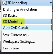
I.3. Change your workspace from Drafting and Annotation to 3D Modeling.
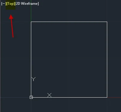
I.4. Draw a rectangle from coordinate point 0,0 to 1,1. Keep in mind that this first part is constructed out of 2D elements not primitives.
I.5. Click on Top in the model space viewport and select SW Isometric.

I.6. Make a copy of the rectangle 1 unit above the existing one. First verify that Ortho is on so that the copy is constrained to the x, y or z axes.


I.7. Join the corners with lines. Try using the 3D Orbit tool to view the three-dimensional box.

I.8. Return to the Top view.
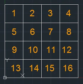
I.9. Array the wireframe box so there are 4 rows and 4 columns with no space between them.
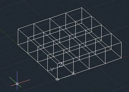
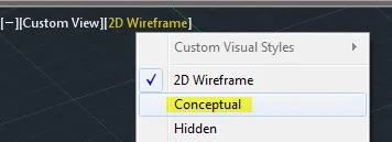
I.10. Change your Visual Style to Conceptual.
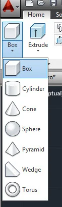
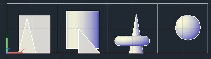
I.11. In Box 1 (upper, left) place a Primitive Box. In Box 2 place a cylinder.
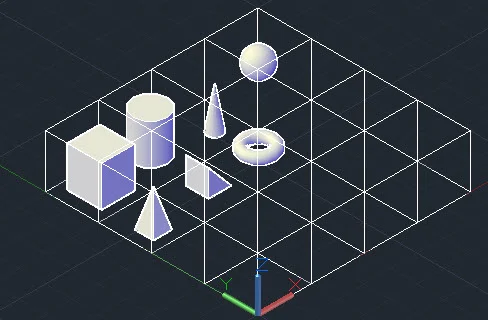
I.12. Continue placing Solid Primitives as shown below.
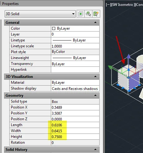
I.13. The objects must fit within the wireframe boxes. Use the 3D Orbit tool and preset views to verify the placement. Keep in mind that you can change dimensional parameters of objects in the Properties window. In the image below the Box has been selected.
I.14. To verify that the object are within the wireframe go to Top, Front and Left or Right views. The view below is a Front view.
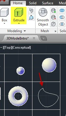
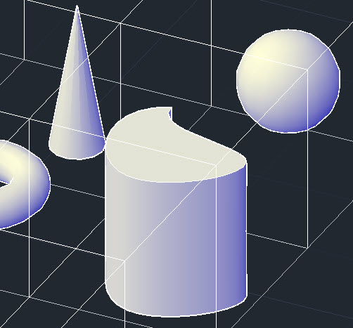
I.15. From top view make a closed polyline in Box 8. It can have straight lines or curved. AutoCAD will default to placing objects on the 0 plane of the Z axis unless an existing object is there. Use the Extrude tool to give the object height. The height dimension is your choice so long as it fits within the frame.
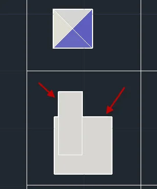
I.16. In Box 9 draw two overlapping primitives.
I.17. Make copies to the two primitives in Boxes 10, 11 & 12.

I.18. Leave the two primitives in Box 9 as is. For the two primitives in Box 10, use the Union tool to join them into one composite object. Click on Union and select both boxes. When this is done, click one of them again. You should see that they are joined as one object.
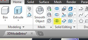
I.19. Use the Subtract tool in Box 11 to subtract one primitive from the other.
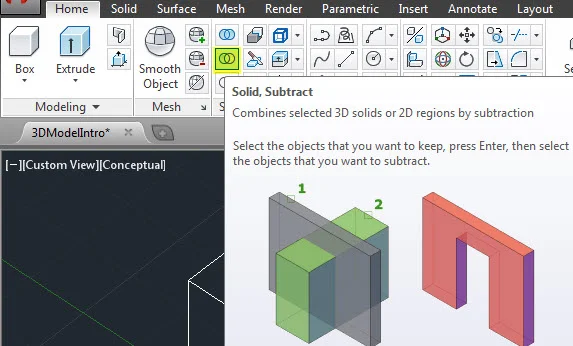
I.20. In the image below the shorter primitive was subtracted from the taller one.

I.21. In Box 12 generate a solid from the intersection of the two primitives by using the Intersect tool.
I.22. In the image below, the shape that remains is the shape of the intersection.

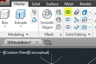
I.23. In the remaining four wireframe boxes explore various three-dimensional operations on the Home ribbon.
I.24. Save your file and upload it to your Google Drive folder. No need to print to pdf.

.
.
.