CCC Architecture
Programs in Architectural Studies at the City Colleges of Chicago
Geometries
The exercises on this page are intended to introduce you to two-dimensional AutoCAD drawing. For this exercise you will be working with a series of two-dimensional geometric constructions using drawing tools. You will also gain experience working with object snaps.
Objectives/Outcomes and Assessment Criteria
Students will acquire and demonstrate: 1.) technical competency in working with layouts, basic drawing tools, coordinate input, object snaps, 2.) sense of craft through precision and care in the presentation of the work, 3.) design aptitude in the ability to solve an organization problem and explore possible solutions, 4.) judgment in the composition of objects within a field. 5.) consideration of limitations and constraints in the problem solving process.
Steps
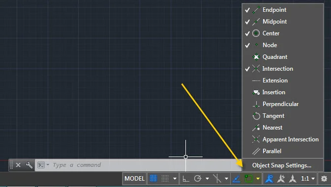
Before starting the exercise, you may want to watch the video below. The video discusses Object Snap settings and operations. Object Snaps help you to be more precise in the way that you draw by allowing you to snap to points like the intersection of two lines or the center of a circle. Please note that the video shows the screen for AutoCAD version 2014. If you are using an newer AutoCAD version, you will find the Object Snap control on the status bar at the bottom of the screen. You can select the object snaps one at a time or you can select Object Snap Settings at the bottom of the list to change more than one at a time. It is not recommended that you turn all of them on, but just the ones you use frequently.
G.1. Create a new file and name the new file by copying the 8.5" x 11" titleblock file. Find the file, right-click on it, choose copy, right-click again, and choose paste. Rename the file to your first name, last name followed by Geometry. Jack Sprat would name his file JackSprat_Geometry. If you uploaded the titleblock file to your ePortfolio, you can download it from there as well.
G.2. Open the new file.
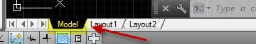
G.3. Click on the model tab to place yourself in model space.
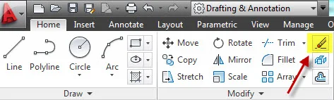
G.4. Erase anything that you currently have drawn in model space. Click on the Erase icon or type E at the command line. Make a window around the group of objects by clicking on two points to form an enclosing rectangle. Press Enter.
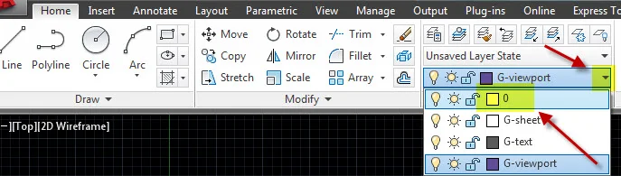
G.5. Get your current layer to Layer 0 by selecting it from the pull-down menu.
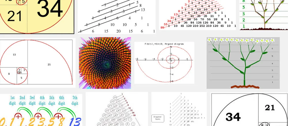
G.6. In this exercise you will be generating a series of geometric compositions. The first one will be a logarithmic spiral which uses the Fibonacci sequence (1, 1, 2, 3, 5, 8, 13, 21, etc.). The concept is that by adding two numbers in the sequence you get the next number in the sequence. For example, 2 is added to 3 so that the next number is 5. The images below illustrate how the Fibonacci sequence works.
The video below describes the procedure.
G.7. Begin with a square that is 1 x 1 units. It can be drawn anywhere in model space. In the image below the 1 x 1 square is shown in a gray tone with an arrow pointing to it. Then draw another 1 x 1 unit square on the right side of the first one. Follow this with a 2 x 2 square above. The next is 3 x 3 on the left, but the one that follows is 5 x 5 below. Continue until you have constructed the squares below. Then construct arcs to generate the spiral pattern. Use the ARC command or click on the Arc icon to draw an arc. Select the Center option first. Then choose a start and end point.

G.8. Next you will be drawing a Golden Rectangle. The Golden Rectangle is believed to have ideal proportions and is commonly used in design. A credit card, for example, has the proportions of a Golden Rectangle.

G.9. Start by drawing a 10 x 10 square using the RECTANGLE command. Your drawing will be in model space so the square will be white and the background will be black. The rectangle should be drawn to the side Fibonacci series drawing. Draw a vertical line from midpoint to midpoint of the top and bottom. Draw a diagonal line from the bottom of the line to the upper right corner.

G.10. Draw a circle with its center at the lower left end of the diagonal line and its radius at the upper right end of the diagonal line.

G.11. Add a line from the lower right corner of the square to the right quadrant of the circle. Complete the rectangle. The Golden Section is shown with a gray tone below. You do not need to include the gray tone.

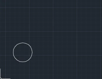
G.12. For the next part you will be working with ARRAY commands. Begin by drawing a circle with a radius of 1 somewhere toward the right of your other objects in model space.
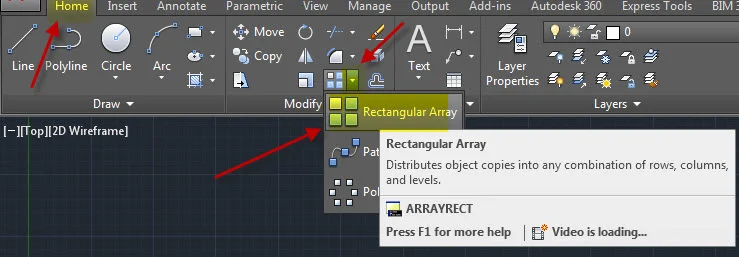
G.13. Type ARRAY at the command line or click on the array icon and select the circle.
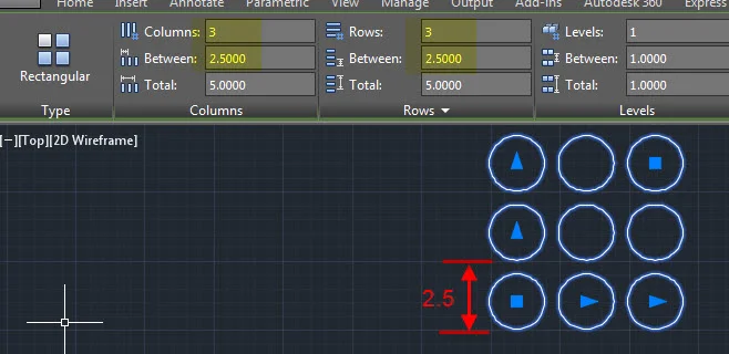
G.14. Array the circle into 3 rows and 3 columns having a spacing of 2.5. The ribbon will change to allow array editing when you click on the circle.

G.15. Inside one of the circles draw a line of any length and angle. The line must fit within the circle.

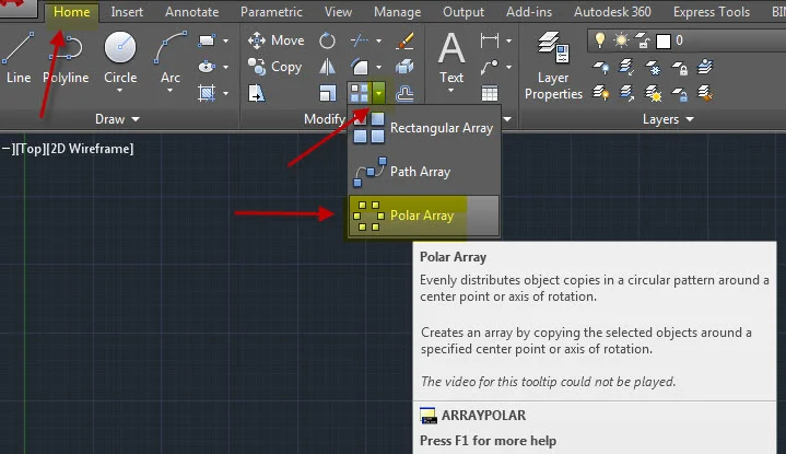
G.16. Use the Polar Array tool to array the line.
G.17. Select the line. When prompted for the center of the array, snap to the center of the circle. Edit the array settings to generate patterns.
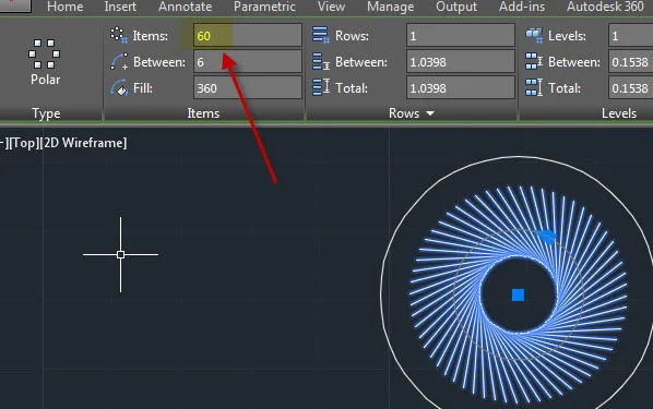
G.18. In each of the 9 circles experiment with polar array patterns using lines, arcs, circles, ellipses, rectangles, etc. Keep your array patterns inside the nine circles.
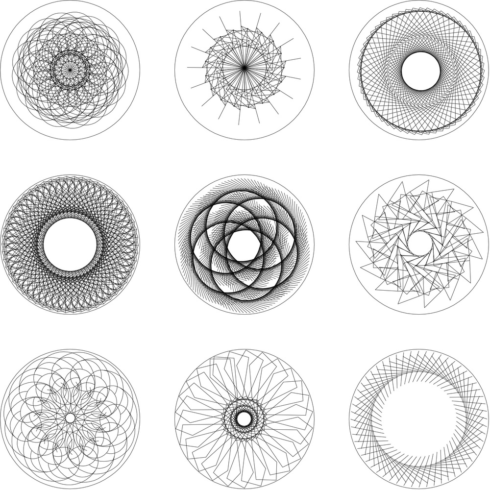
G. Flores_Polar Array Composition
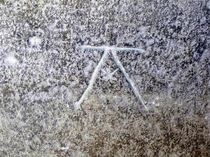
G.19. In the next geometric composition you will be designing your own mason's mark. Mason's marks are symbols used to identify the work of a stone mason. An example is shown below. You can use Google to search for images of other masons marks.
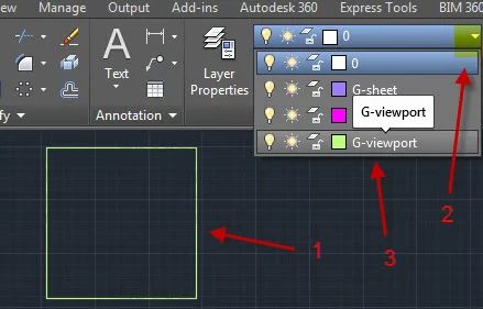
G.20. Begin by making a 7x7 square. Put the square on the viewport layer so it will not print. To move something from one layer to another, 1.) select the object, 2.) Click on the pulldown arrow in the Layer panel, and 3.) select the layer you would like to move the object to.
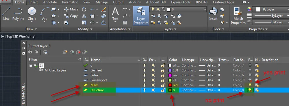
G.21. Create two additional layers using the Layer Manager. Name one layer Structure. Assign color 8 to the layer, and check the printer icon so that the layer does not print. Create another layer called Mark. Assign color 1 which is red to the layer, and make sure that the layer will print by checking the printer icon.
G.22. Set you layer to Structure. Precisely in the center of the square make a circle with a radius of 3. You can draw a temporary X from the corners of your square to locate the center. See the image below.
G.23. The image below show some examples of masons' marks. The light lines represent the structure. The dark lines represent the mark. Draw the structure for your mark as shown in one of the drawings. There are three types shown below: the rotated square, the star pattern and the six circles. Choose one to be the structure for your mark.
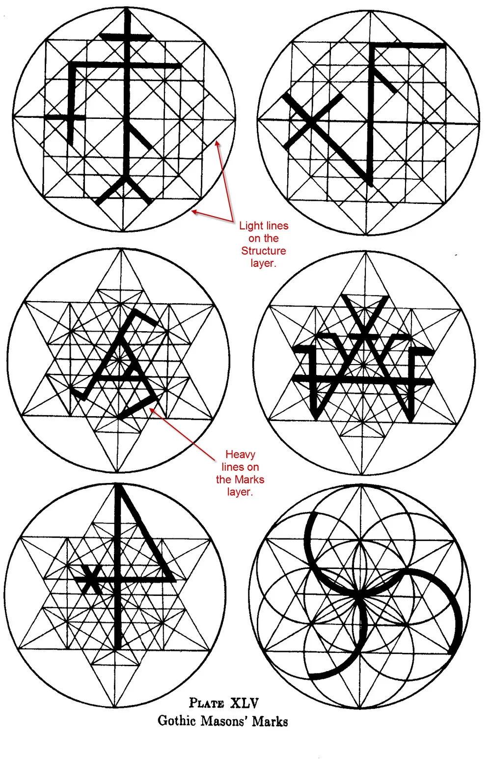
from the Geometry of Art and Life by Matila Ghykla
G.24. Draw the structure you have chosen. Begin by drawing a circle with a diameter of 6 precisely in the center of your 7 x 7 square. If you draw an X across your square, you can easily locate the center of the circle.
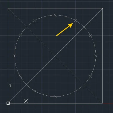
G.25. You may find it useful to use the divide the circle depending on the structure pattern you have selected. The circle below has been divided into 12 divisions. Before dividing the circle into 12 equal divisions you will need to change two settings. One is the setting for the point display mode. The current setting is 0 which means that nothing will appear on the screen. Changing the value of PDMODE to 3 will produce x's. The other setting is the point display size. Changing the value of PDSIZE to 0.125 will make the x's 1/8 of a unit. To divide the circle, use the DIVIDE command, select the circle and input the number of divisions. The small x's that appear on the circle below are node points.
To snap to those node points you will need to turn on the Node object snap. To set your object snaps right-click on the Object Snap icon on the status bar. You may find that turning on the Quadrant object snap is useful for this exercise.
Complete all of the lines that make up the structure.
G.26. Design a Mark. Your mark will be drawn on top of the structure.
G.27. Change your layer to Mark. Draw the mark that you have designed. All lines and arcs must be on top of the lines of the structure and must snap to the intersections of the structure. The examples above are offset to one side of the structure lines. Yours will be on top.
G.28. Prepare to print your sheets. Go to Layout 1 by clicking on the tab at the bottom of the screen.
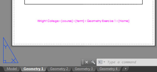
G.29. Change the name of the Exercise to Geometry Exercise 1 by double-clicking on the text string. Click outside the text when you are finished editing the text.
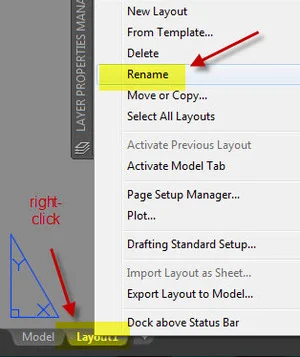
G.30. Right-click on the Layout 1 tab to rename the layout. Change the name to Geometry1.
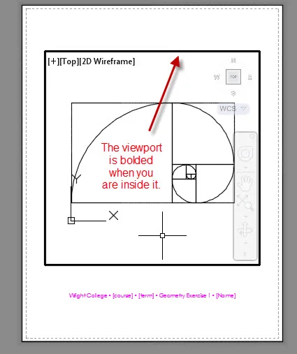
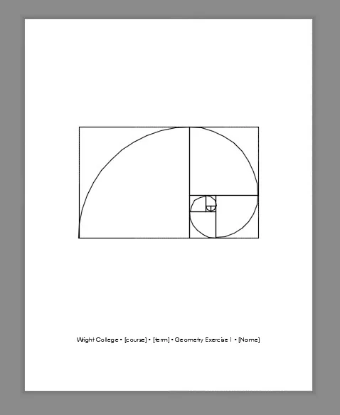
G.31. Double-click inside the viewport. You should notice that the viewport is bolded. Use the Extents option of the ZOOM command to see all of the work in model space. Type ZOOM at the command line and then select Extents. Everything in the model should then fill the viewport. Use the Window option of the ZOOM command to enlarge the logarithmic spiral. Fill the space of your viewport with the logarithmic spiral. Double-click outside of the viewport to make changes to the layout or text.
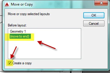
G.32. Make a copy of the layout by right-clicking on the Geometry 1 layout and choosing Move or Copy. Select (move to end) and check the box to Create a copy.
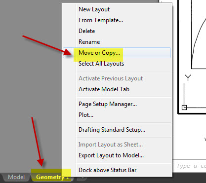
G.33. Select (move to end) and check the box to Create a copy.
G.34. Rename the layout to Geometry2. Change the text string to Geometry Exercise 2.
G.35. In the viewport use the Zoom option of Extents to view all of the model space work. Then zoom to the Golden Rectangle composition. Center and enlarge to fill the viewport.
G.36. Repeat the steps above for the Polar Array circles and the Mason's Mark. There will be four layouts as shown below.
G.37. Place the file called wright.ctb in the correct folder. The instructions for this can be found in the Page Setup and Layout page of this website. Look for a description beginning at TB.19 on that page.
G.38. Print all four layouts to to pdf. The preview for Geometry 1 should appear similar to the image below. Notice how the viewport square does not appear and notice how the text is black. Name each sheet with the same name as the drawing file. The first layout would be named with you name followed by Geometry1.
G.39. Save your drawing file. Close your file.
G.40. Upload the drawing file and the 4 pdfs to your Google Drive folder.

.
.
.